|
The Lotus 25 was a revolution in Formula 1, it was the first monocoque car in Grand Prix and it was so successful that, within 7 years, all but one team had abandoned the spaceframe chassis and adopted the monocoque. The monocoque was more rigid and lighter than the spaceframe, an advantage that showed on the track.
The Lotus 25 was introduced in 1962 where it gave Jim Clark 3 wins, including his first Grand Prix win at Spa Francorchamps. Unfortunately, mechanical problems also caused 4 retirements, including the famous oil spillage at East London in South Africa.
In the 1963 season the majority of the reliability issues had been worked out and Clark went on to dominate the season. Of the 10 races that year, Clark won 7 and as only the driverís best 6 results counted in the championship, Clark had the maximum points available.
Iím too young to have seen Jim Clark race, I wasnít born until 5 years after his untimely death, but I grew up hearing and reading about him. My dad was a huge fan and in his mind Jim Clark was the finest racing driver the world has ever seen, a sentiment expressed by many who saw him race. The fact that he was Scottish, as I am, and that he is my dadís favourite driver helped me decide to build this kit.
Kit Contents
The kit comes in the usual Tameo box and contains white metal, photo-etched & turned parts as well as rubber tyres and springs for the suspension.
The white metal parts cover the major components, including the chassis, body, seat, engine, gearbox and suspension uprights. The photo-etch covers the majority of the suspension parts as well as the air intake cover and pedal box. The wheels, exhausts, suspension dampers, brake discs and air intake ports are all made of turned aluminium.
The decal sheet for this model is pretty small (no huge sponsors logos on a car of this era) but well printed by Cartograph.
Preparation and body
I started by cleaning the flash and mould lines from body and chassis. As with most Tameo kits the white metal parts are very well cast with only minimal cleaning required. I then sanded down the body and chassis, starting with 600 grade sandpaper and working up to 4000 grade Micromesh, this gave a nice smooth finish to the body.
There are several holes that need to be drilled in the chassis; 2 suspension mounting points for each of the front lower wishbones, 4 suspension mounting points for the rear upper and lower wishbones and 2 on each side of the rear of the car for the rear suspension braces. All of these holes were drilled with a 0.65mm bit.
I then sprayed the body and chassis with white primer, once this had dried I sanded them with 12000 grade Micromesh and then sprayed them with Tamiya X5 Green.
Sub Assembles
The majority of the assembly is based around the chassis so whilst that dried I set to painting and assembling the other components
The front and rear suspension uprights were cleaned and painted matt black as per the instructions.
The gearbox I painted with a mixture of Tamiya XF-16 & light grey, the instructions call for gunmetal but donít give any specific reference. The rear of gearbox was painted Tamiya XF-16 and glued to the rear of the gearbox. I then gave the complete gearbox assembly a wash of thinned black ink then drybrushed it with the original colours.
|
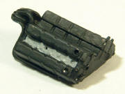
The radiator/nose section I painted with the same XF16/Grey mixture as the gearbox, this part is later glued to the front of the chassis so I made sure the cut out area was clear of any flash/moulding defects. I glued the cylinder heads to the engine block/exhaust manifold section and painted the heads with a darker XF16/Grey mixture. The cam covers and exhaust manifold were painted black as per the references I had. |
|
With the throttle/airbox component I decided to leave the upper and lower sections as bare metal and pick out the piping around the side in matt black.
I then assembled pedal box as per the instructions. The chassis bracket I painted with a lighter version of the XF16/Grey mixture Iíd used previously.
Note: This part should be painted as the same colour as the interior of the chassis, the instructions call for aluminium but I found it a bit too bright so I dulled the colour with a small amount of light grey.
The pedals and pedal brackets are supposed to be chromed, fortunately the parts are already nicely chromed on the photo-etch fret. The 2 pedal brackets are slightly different, but the instructions clearly show which is which.
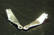
The front upper wishbones are made of white metal, but according to the instructions they are supposed to be chrome. To get the chrome effect I decided to try polishing the parts, I started with a brass brush on a rotary tool then polished with Micromesh, up to 12000 grade. This gave a nice smooth finish but it was more of a satin finish than true chrome. I the end I used Bare Metal Foil which looks much better and replicates the chrome effect very nicely.
|
I also drilled out the top upright mounting hole with a 0.8mm drill bit. |
|
I then painted the front of the dashboard dark red and the rear with the same XF16/Grey mix that Iíd used on the pedal box chassis brace. The dials I painted with matt black and then picked out the brackets, on the rear of the dials, with aluminium.
Assembly onto chassis
By now the chassis was dry and I could get started on assembling the various components onto the chassis. I started by painting the interior of the chassis with the light XF16/Grey mix that Iíd used on the dashboard. This aluminium colour extends up the inside of the chassis and over onto the edge, thereís a clear line moulded on the model that shows where the aluminium section ends.
|
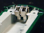
The pedal box fits into the chassis in a recess at the front, itís a fairly tight fit and I had to scrape some of the paint off the surfaces. |
|
The suspension components are already chromed on the fret so no painting was necessary. I had to file down the locating pin on the rear of the front, lower wishbone as it has to fit through a small photo-etched bracket. Having done this, the parts fitted easily and I aligned them so that both wishbones were horizontal.
I then moved on to the uprights and upper wishbones. The uprights are not vertical, they lie back at a pronounced angle, take care to align the uprights so that they line up properly. Also, ensure the uprights fit well into the locating holes on the wishbones, otherwise the wheel wonít fit properly, as I discovered, thankful before Iíd done anything else.
I then attached the radiator piece to the front of the chassis, added the photo-etched radiator grille to the front and did some detail painting on it.
I went on to fit the dashboard, seat, gear stick and gearbox gate. The seat and gear knob were both painted the same colour of red as the dashboard. At this point I noticed that there were no seat belts in the kit, at first I thought that this was a mistake, many of the reference photos I had showed seat belt fitted to the car. After re-watching the footage of Clark racing, I realised that the car didnít have seatbelts, in fact none of the cars of that era had belts. It really puts the risks that these men took into perspective. We forget, in this age of 6 point harnesses and safety cells, just how dangerous motor racing was in this period.
The gearbox fitted easily into the rear of the chassis, but I couldnít get the cylinder head assembly to fit, the pegs donít align with the holes on the gearbox. I ended up cutting the pegs off the cylinder head assembly. I then drilled out the exhaust mounting points on the rear of the exhaust manifold with a 0.45mm drill bit.
I now started building up the rear suspension, I fitted the rear lower suspension wishbones, fed the driveshafts though the uprights, glued the upright to the lower wishbone and glued the driveshafts to the holes in the gearbox. The uprights look identical, but they arenít, thereís a small depression on one side of the upright, this side faces forward so the suspension brace can fit into the depression. Be careful of this as it isnít clear in the instructions until later.
The suspension struts are each made from 2 turned parts with a section of spring cut to. Cut the spring slightly longer than necessary and remove a small piece at a time until the strut is the correct length. The struts were then fitted between the chassis and the lower wishbone.
The anti-roll bar and tie rods complete this part of the rear suspension, I opened up the hole on the tie rods to make sure they fitted on the anti-roll bar. I cut the tie rods to length once they were fitted to the anti-roll bar, there are no markings on the part as to where to cut.
I then fitted the exhausts into the holes I had previously drilled and fitted the photo-etched exhaust support bracket.
The coolant pipe that runs from the radiator to the engine is very prominent on the real car and is covered in red insulation where it passes the driver. I used masking tape, painted red, to simulate the insulation and painted black stripes to duplicate the straps on the real car.
|
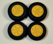
When I came to assemble the wheels, I found that the front wells were a bit narrow, so I made spacers out of sheet styrene. I then assembled the 2 parts of each wheel and fitted the white metal inserts into the front of each wheel. I then primed them and sprayed them with Tamiya X8 Lemon Yellow which looked like a good match with the yellow on the decals. Once the paint was dry I fitted the wheels to the tyres and glued the chrome trim to the fronts of the wheels. With hindsight I should have filled the gap between the turned part of the wheel and the white metal insert.
|

|
 |
|
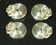
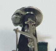
The brake callipers are formed from 2 parts, the calliper itself and the piston, these were glued together and attached to the turned brake discs. The callipers were then painted white and washed with a light grey to bring out the detail. The brake assemblies were then glued onto the axles, you have to be careful here, the callipers are mirror images and must be fitted to the correct side of the model. The assembly has to be fitted so that the small hole for the brake pipe is towards the top of the wheel. |
 |
 |
Before fitting the steering column and wheel I applied the decals to the instrument panel, the position of them on the model seems to be reversed from the drawing in the instructions. The steering wheel is composed of a plastic rim glued to photo-etched spokes, I painted the rim the same red as the seat and left the spokes unpainted. The steering column is a thin piece of wire supplied in the kit and it fits easily through the hole in the instrument panel and connects to a small hole in the pedal box.
Finishing and Detailing
I decided that since the model could be displayed with the body off, it would be nice to add some extra detail to the model. I decided to add the wiring that I could see clearly in the reference photos, the throttle cable is very obvious, it runs from the throttle pedal, up around dashboard, behind roll bar and into the centre of the engine. The cable is red most of the way, and steel at the pedal end, I used white cotton thread, dyed with red ink and painted steel at the end.
There are also wires running from the engine to the nose, using black thread I added wires alongside the throttle cable then down the side of the car into the nose. I also used black thread to add wiring to the back of the instrument panel, 2 of which I ran into the engine and 3 of which I ran to the nose.
The spark plug leads are shown in various references as both yellow and black, I decided to use yellow, as it shows more clearly against the black of the cam covers. I also inked the lower part of the lead black to simulate the plug boots.
The addition of the rear suspension braces, track rods, brake hoses, air intakes and wheels completes the chassis assembly.
I normally apply a clear coat to my models both to protect the decals and to give an extra shine but I decided not to clear coat the body and chassis of this model. Cars of this age didnít have a showroom gloss finish like modern F1 cars so I polished the model with Micro-Gloss from the Micro Mesh craft kit.
All that remained was to fit the mesh intake cover, apply the decals to body & chassis, fit the vac-formed windscreen and attach the mirrors. The decalling was a real pleasure, being used to the multiple sponsors decals on modern F1 cars, it was a delight to have so few decals to apply. Of course, it does mean that any flaws in the paint are easy to spot. (lotus25_40.jpg, lotus25_41.jpg)
Display Stand
I wanted to retain the ability to display the model with the body on or off the car, so I built a small stand to display the body panel. I decided to go for a trestle style of stand so that the panel could be displayed horizontally alongside the car.
The stand was built from 1mm mains cable bent into 2 trestles at either end to support the body and 3 cross members to provide rigidity. I then sprayed the stand matt black and fitted the straps which are made from electrical tape and seat belt adjusters from a Renaissance photo-etched seat belt accessory.
Conclusion
The Tameo WCT63 is another excellent kit from Luca Tameo, who really sets the benchmark for 1/43 Formula 1 kits. As this is my first Ďclassicí F1 model (all my others have been relatively modern) Iím very pleased with how it turned out. (lotus25_45.jpg to lotus25_51.jpg)
The purity and delicacy of the cars from this era is something that has been lost from Formula 1 with the advent of sponsorship and aerodynamics. Modern F1s are a technical tour de force, no doubt, but where they are purposeful and efficient, the Lotus 25 is beautiful and elegant and sometimes aesthetics count for a lot.
The kit builds into an attractive and accurate replica of the real car with no real problems other than the width of the front wheels, and the end result is a fitting tribute to the genius of Colin Chapman and the skill of Jim Clark.
|