|
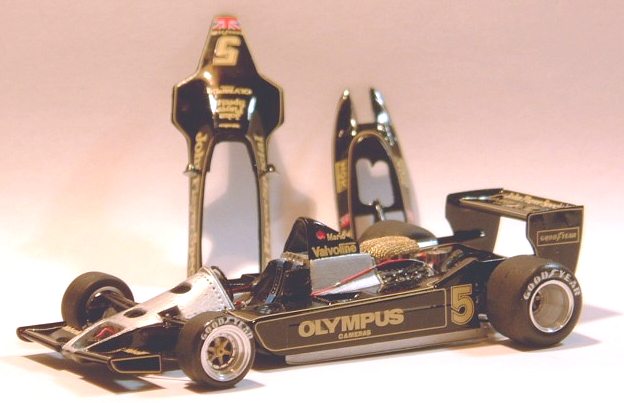
Like many motor sport fans, I grew up watching Formula 1 races on TV and I loved it, the exotic locations, the sound of the engines, the bright livery of the teams, but most of all I loved the cars. Those fantastic pieces of machinery that looked nothing like any road car, they fascinated me with their engines in the rear and their wings and wide tyres. One car, above all, stuck in my memory, the John Player Special Lotus. This car wasn't brightly coloured, it was black, mean and moody, this was a car that meant business. So with that in mind I set out to build one of my favourite Grand Prix cars, the Lotus 79, but first some history.
Lotus 79 Background
The Lotus 79 marked the culmination of Colin Chapman, Peter Wright and Tony Rudd's experiments with ground effect aerodynamics. Its predecessor, the Lotus 78, had been fiercely competitive in the 1977 season, giving Mario Andretti 4 wins and Gunnar Neilson a further 1 win. Only its poor reliability let the team down, possibly costing Andretti the championship that year.
The 79 built on the aerodynamics of the 78, like the 78, the side pods were shaped like inverted wings to generate down force and the sliding skirts on the side pods sealed the underside to prevent the air leaking out the sides. Regulation changes meant that the triple fuel cell of the 78 could be reduced to a single cell behind the driver, allowing a reduction in frontal area, reducing drag. The extra down force from the body meant that a smaller rear wing could be used, further reducing drag, the end result was a championship win for Andretti and a constructor's title for Lotus in 1978.
Kit Contents
I'd picked the Tameo kit of this car because it had removable panels and offered high levels of detail and having built Tameo kits in the past I knew that they were of a very high quality. What I didn't realise was just how many parts their WCT series kits actually contained, when I opened the box and spotted the tiny springs for the suspension I had my doubts as to whether my modelling skills were up to the task.
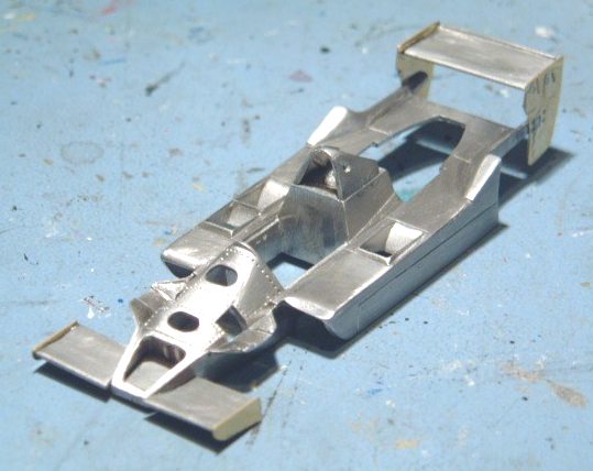
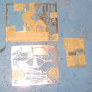
As this is a Tameo kit, there are no resin parts, everything is white metal, photo-etch or turned metal. All of the major parts (chassis, body, body panels, front and rear wings, gear box, engine etc) are very nicely cast white metal with virtually no flash and only slight mould lines. The turned parts cover the wheels, wheel hubs, gear stick, suspension struts and velocity stacks. There are also 3 frets of photo-etched parts for suspension arms, seat belts etc.
Unlike the newer Tameo kits there is only one set of decals in this kit, so no mistakes allowed. The instructions are up to Tameo's usual high standards, consisting of 8 pages of A4 with clear assembly diagrams and colour suggestions for all of the parts (some of which aren't entirely accurate but you can't have everything), if only more manufacturers provided instructions as good as these.
Body Parts
After cleaning up the flash and mould lines on the body and the front and rear body panels I set about sanding down the surfaces of the parts. Unlike resin, white metal has a definite grain to it which can show through when the parts are painted. Some preparation at this stage can save a lot of work when it comes to painting. I start off with 600 grit paper, move on to 1200 grit and then finish off with Scotchbrite which gives a smooth finish to the surface.
|
The white metal front wing was attached to the body and the photo-etched end plates then attached to that. The mounting points for the rear wing required a small amount of filing to allow the end plates to sit flush against the body, but once this was done assembling the rear wing was simple, cyanoacrylate glue was used to fill the small gaps in the end plate mounting points.
|
|
There's a small frame that fits at the rear of the engine bay, according to the instructions this should be silver but my references showed it to be black so this was attached to the body at this point (this turned out to be a bit of a mistake). The roll bar assembly was also attached at this point.
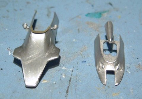
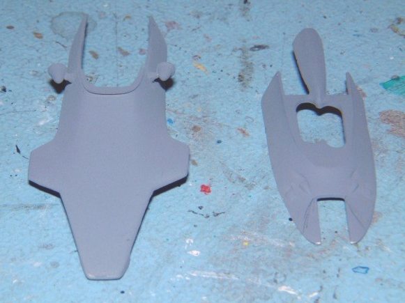
The wing mirrors and air deflector were attached to the front body panel.
|
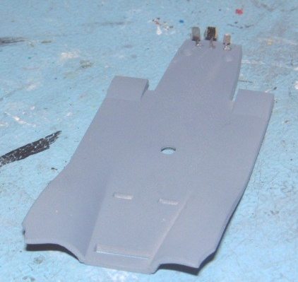
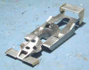
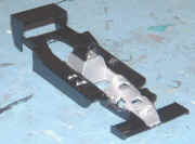
The rear body panel doesn't have any parts to be attached and just needs to be cleaned up. The chassis was cleaned up and the 3 pedals attached to it.
|

|
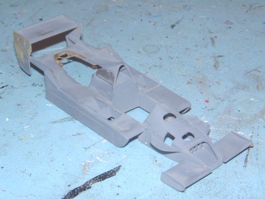
All of the body parts were then primed and the body, front body panel and rear body panel were sprayed with Tamiya X-1 gloss black and put aside to cure. The chassis was sprayed Tamiya XF-1 flat black and put aside.
Gearbox & Rear Suspension
|
I masked off the photo-etched parts that were to be painted a different colour and sprayed the exposed parts flat black. The painted parts were given a coat of gloss varnish, then a coat of matt varnish to protect them.
|
|
|
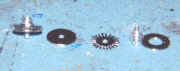
Whilst the photo-etched parts were drying I assembled the rear brake discs. The discs are made from 3 photo-etched parts and a turned aluminium hub the entire disc assembly was given a few washes of Tamiya X-19 Smoke to dull it a little. I then attached the photo etched brake callipers which I had previously painted matt black.
|
|
|
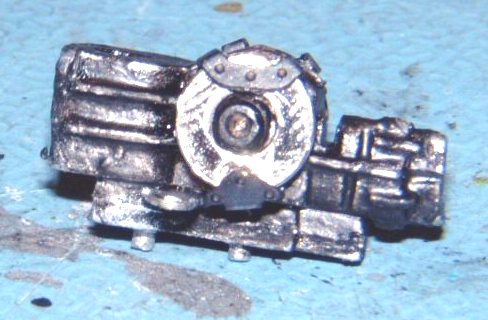
I painted the gearbox matt black, according to the instructions this part should be left black but I drybrushed some gunmetal over it then gave it a black ink wash to bring out the detail. I glued the lower strut mount and the lower gear box plate to the gearbox and then glued the completed brake disc to the assembly.
|

|
|
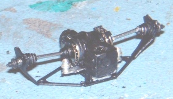
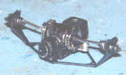
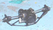
The rear wheels hubs are made from two turned pieces glued together, one forming the wheel hub, the other forming the drive shaft boot. The two hubs were then fitted to the lower rear suspension arm which I had already sprayed matt black. Tameo thoughtfully include a small jig, allowing you to bend the rear suspension to the correct angles.
|
|
|
|
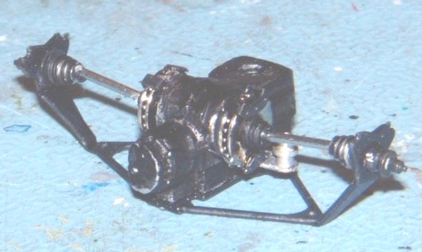
The next stage is to add the upper suspension arms, suspension actuators and various braces, all of which are painted matt black. The struts are lovely little pieces of engineering, each one is made from 2 turned parts and a small spring, the spring has to be cut to length so a bit of care is required here; you can't add back what you cut off ! I ended up removing 2.5 turns from each spring and fitted the struts in place. There's a small cylinder attached at this point (fuel pump perhaps?) as well as a photo-etched heat shield, completing the rear suspension/gear box assembly.
|
|
|
|
Engine Assembly
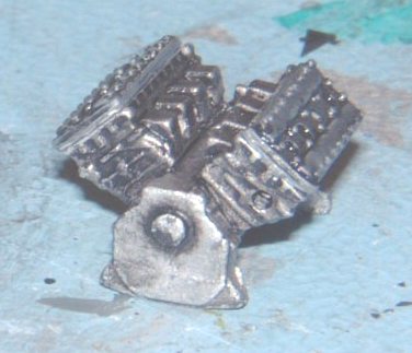
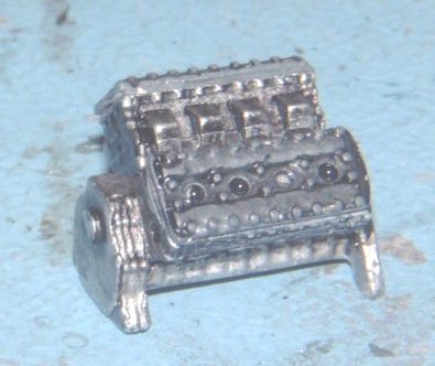
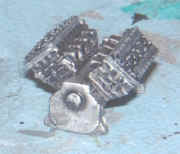
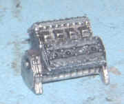
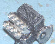
The engine in the Lotus 79 was the Ford Cosworth DFV used in many Grand Prix cars of this era and is well represented here. The main engine is in five parts; the crank case, 2 engine blocks and 2 cylinder heads. I painted the crank case Tamiya XF-16 aluminium and gave it 2 black ink washes, the engine blocks I painted matt black and lightly drybrushed them with aluminium, the cylinder heads I painted gunmetal and washed with black ink. I then assembled the individual parts to form the main engine assembly.
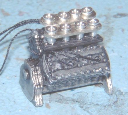
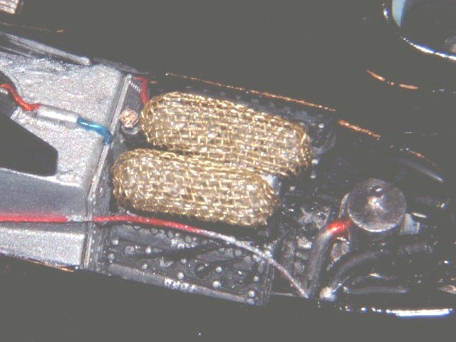
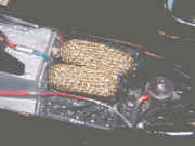
The intake mount is aluminium in the centre and matt black on either side. The velocity stacks mount on to the intake, on the real car the velocity stacks are surrounded by a gauze air filter, the kit doesn't contain these filters but I decided to make them.
|
|
|
|
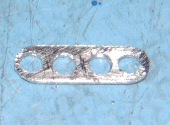
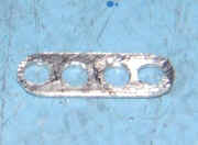
I made supports for the air filters from a piece of spare photo-etch (part 13 used to bend the rear suspension and no longer needed), cut into a rectangle 11mm x 3mm and filed the corners until they were round. I then drilled four 1.6mm dia holes spaced 2.7mm apart.
|
|
|
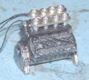
The air filters I made from fine brass gauze, using a small former made from Milliput to shape them. I had some difficulty locating the gauze so the air filters weren't fitted until later in the build. With hindsight, the metal I used for the support looks a little thick, some thinner fret would have been better, but
the supports won't be visible once the gauze is attached so no harm done.
I also added spark plug leads to the engine, the leads were made from black cotton thread and run from each spark plug to underneath the intake mount. Don't do what I did and attach the plug leads before putting the "Ford" decals on the cam covers !. That completed the engine assembly.
|
|
|
Wheels
The front wheels consist of two turned pieces with a photo-etched insert for the spokes of the wheel. The photo-etched part is painted gold and sandwiched between the two turned parts and the whole lot glued together, a photo-etched rim is then fitted from the front to complete the wheel.
The rear wheels are similar except that there was no insert, the wheel was solid on its rear face with no place to put an insert. The rear wheels are very deep, like most F1 cars of this period, but the spokes are clearly visible in the various reference photos I have, so I decided to add the spokes to the wheel. I cut a six spoke insert from a sheet of acetate, painted it gold and glued it to the back of the photo-etched rim and then glued the whole thing inside the rear wheel, having first painted the inside face matt black. I don't know why Tameo didn't include the spoke insert in the kit, but it should definitely be there.
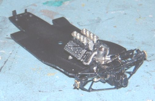
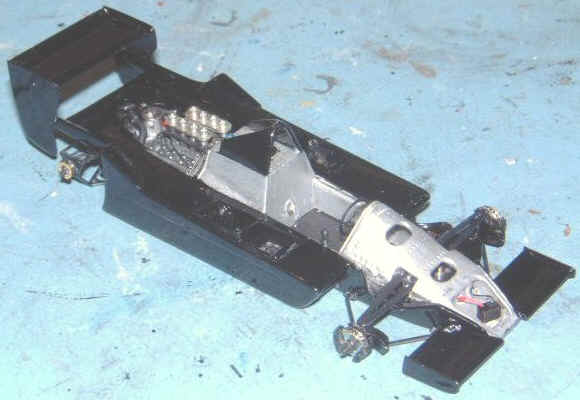
Chassis Assembly
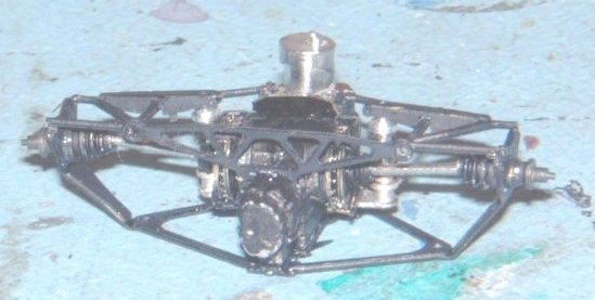
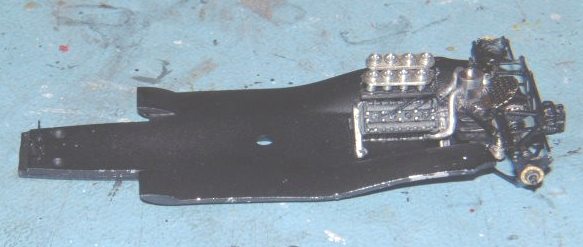
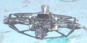
The engine assembly fits easily into slots on the chassis and the gearbox/rear suspension attaches to the engine (as it does in the real car). The gearbox has a hole that fits over a small peg on the engine to attach it, I drilled the hole in the gearbox a little deeper to give a good contact and also pinned the engine and gearbox together for added strength.
The instructions suggest adding the pipes from the cylinder on the gearbox during the gearbox assembly, but I attached them at this point so that I could be sure the pipes wouldn't foul on the engine. I also attached the exhaust pipes to the engine a this stage, in fact I almost attached them upside down, but realised my mistake before gluing anything, whew.
Body Assembly
|
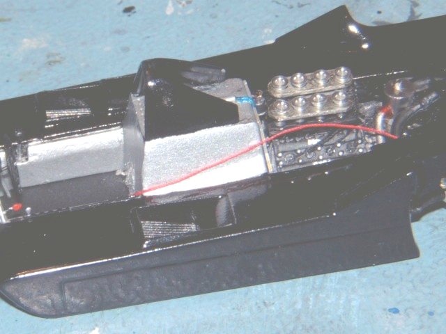
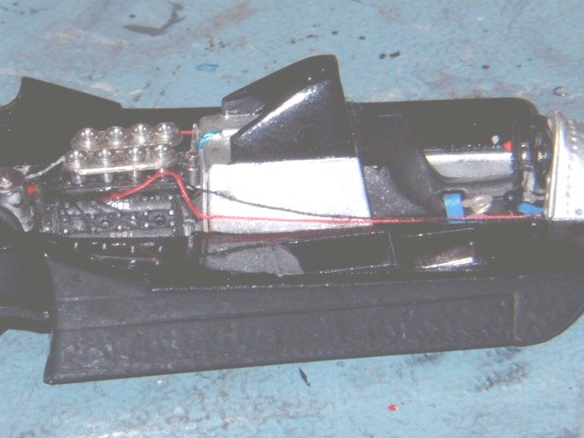
The instructions state that the body shell should be painted black, but the nose section, the cockpit interior and the fuel cell behind the driver should all be painted aluminium. Rather than mask and spray the shell, I decided to brush paint the aluminium areas. I used Tamiya XF-16 thinned with a mixture of alcohol, water and Daler-Rowney flow enhancer, the flow enhancer helps to ensure that no brush marks are visible once the paint cures, although metallic paints show fewer brush marks than solid colours anyway.
|
|
|
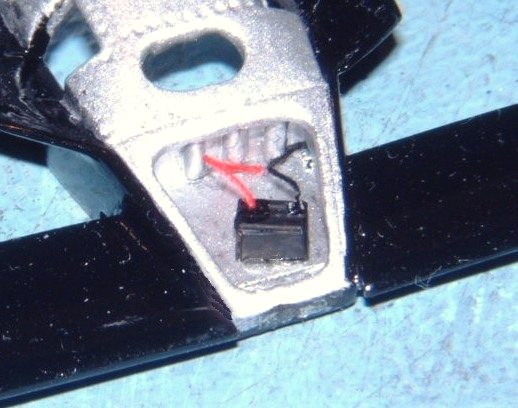
I then fitted the small battery to the nose of the car, this is formed from two photo-etched pieces, one folds into the basic box and the other is the battery top. I also added red and black wiring, again made from pieces of cotton thread.
|

|
|
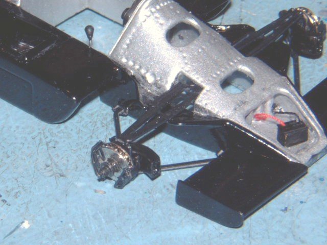
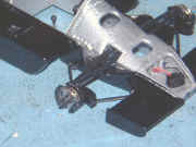
The front brake discs were assembled in the same way as the rear brake discs and the brake callipers attached as before, the disc assembly then fits on to a turned metal hub. The brake/hub assembly then fits to the front suspension arms which are painted matt black and bent as shown in the instructions. I then fitted the suspension arms to the body (leave the upper suspension arm free to move, allowing you to adjust the height of the front wheels). I then built the front struts in the same manner as the rear (again being careful when trimming the springs) and attached the struts to the suspension arms from below. I then attached the remaining details to the body; gear lever, dash board, steering wheel & column etc, finishing the body assembly.
|
|
|
Final Assembly & Detailing
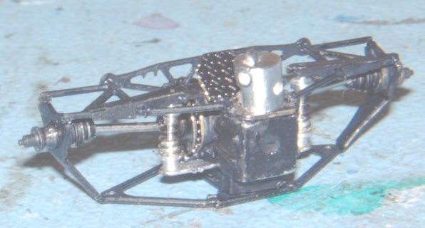
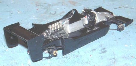
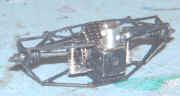
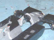
The chassis fitted into relatively easily, although a bit of fiddling was needed to get the exhausts to sit above the brace at the rear of the body. To be fair, the instructions do say that this brace should be attached after the chassis assembly is fitted to the body and I have to admit it would've been easier that way.
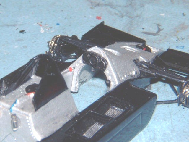
The seat, complete with photo-etched seat belt was glued into place and several cables were added running from the cockpit to the engine bay. I didn't attempt to add every wire on the real car, but the three cables from the cockpit were very obvious in the reference photos I had and they were fairly simple to add.
|
I also managed to find some brass gauze at this point and added the air filters to the engine. I then glued the wheels on, attached the side skirts and glued the upper suspension arms in their final positions.
|
|
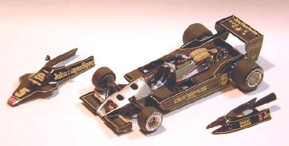
I then applied the decal to the body panels. As the car is composed mostly of flat panels there are no really tricky compound curves to deal with, all of the decals applied easily and Tameo even have the foresight to split the "John Player Special" decal into two parts so that the builder doesn't have to cut it himself.
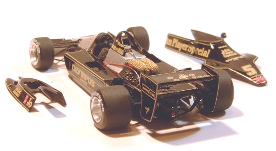
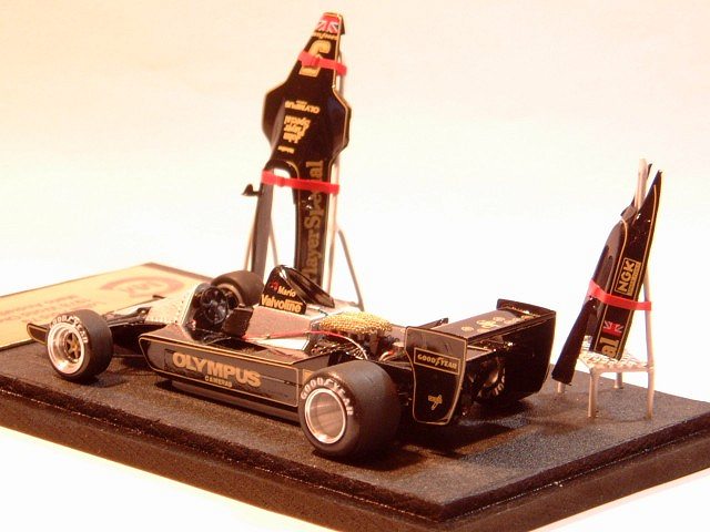
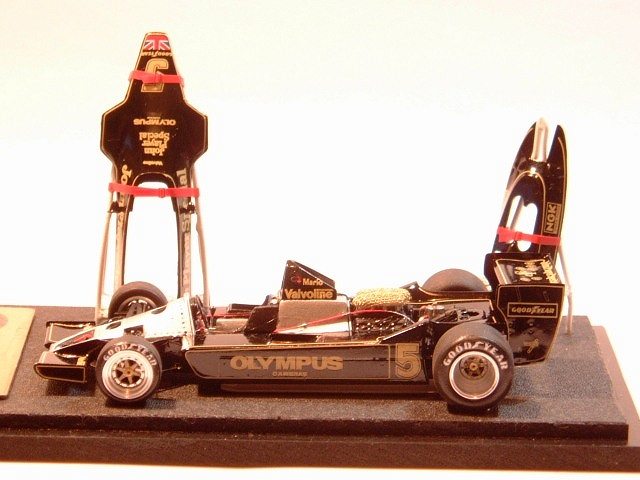
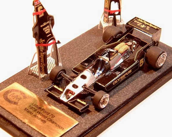
The final model is a very nice representation of the actual car and looks pretty accurate to me.
Displaying the Model
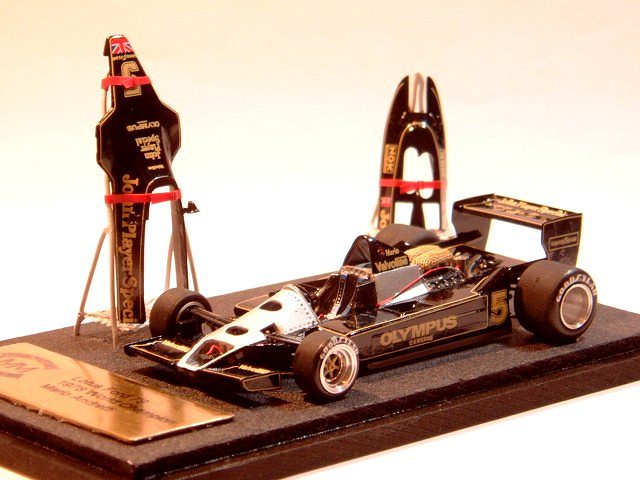
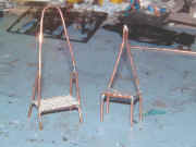
Having put so much effort into the details of the engine and wiring, I thought it would be a shame to display the model with the body panels on so I decided to make a couple of stands for the removable panels. Rather than resting the panels on trestles as they probably would have been in the pits in real life, I decided to make a more complex stands.
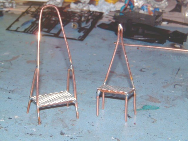
The stands had to support the panels and hold them upright so that all the detail could be seen from the front of the case. I also wanted to retain the option of fitting the panels to the car at a later date, so
|
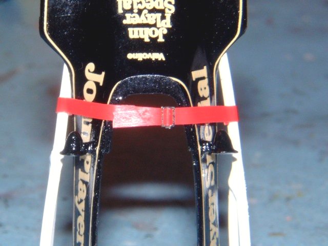
I couldn't glue the panels to the stands which meant some kind of strap holding the panels in place. In the end I build the frames from 1.5mm copper mains cable soldered together and made the mesh platforms from car body repair aluminium mesh.
|
|
|
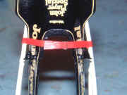
The straps are made from electrical insulating tape and the buckles are from a Renaissance seat belt kit, and yes, the straps do work. One end of the strap is attached to the centre of the buckle and the other part of the strap is threaded through the buckle so I can remove the panels if necessary.
|
|
The whole lot was mounted on a base and finished off with a small brass plaque with the model's details on it.
Conclusion
All in all this was a very enjoyable kit to build, as with most Tameo kits it went together very easily with no real problems. The only omissions were the air filters and the lack of spokes for the rear wheels, both easily rectified. This is a kit that would lend itself to further detailing and as my meager efforts show even a small amount of extra detail adds a lot to this model.
Thanks once again to Peter Radcliffe and Mario Covalski for their encouragement and all their hard work in maintaining Amazing 43.
|